
Quite often customers ask me, whether or not a connector would work for a certain set of electrical signals. Today everything is fast, especially the data rates. And whatever is above 1 Gbps is transmitted in differential pairs in order to get rid of common signal grounds and subsequent ground bounce which reduces the “readability” of the digital signal. And this is true inside the box between boards as well as outside the box going box-to-box with cables.With differential pair technology, we have to look into two things.
First we need to understand how to set up the pinning on the connector. If we use backplane connectors such as Impact™ or Impel™ for speeds above 6 Gbps, 10 Gbps or even 25 Gbps, we don’t have to think about pinning. The connector designers in cooperation with the signal integrity gurus have already considered the best way of packing the transmission lines into these connectors.
This is also true when we use I/O connectors such as SFP+, QSFP+ or iPass+™ HD running between 6 Gbps and 14 Gbps today and hopefully (on shorter distances) 25 Gbps tomorrow. The crux comes when one of these connectors is at the limit with regard to speed, when transmission links are getting longer, and when restrictions in cross talk or common mode transformation become critical.
If we have lower speeds or LVDS (Low Voltage Differential Signaling) we may use standard connectors with no dedicated pinning, but this is worth another blog!
Second we need to understand what a digital signal is all about, how it is composed and what the criteria are to fully understand the influence of a connection within the transmission line.
Let’s start with the basics which go back to Mr. Shannon and Mr. Fourier. The Shannon theorem says that the maximum you can do is to pack 2 bits into a full sine wave. This relates also to the digital NRZ (Non Return to Zero) coding. There are other semi-analog coding schemes like PAM4 where you have to read four different voltage levels out of your signal, but this is too deep for today. Just to let you know that the 10 Gigabit Ethernet transmission over an RJ-45 works this way.
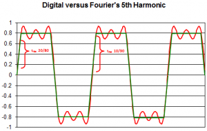
Let’s stick with NRZ and wonder, why digital people like square wave signals: A square wave signal shows a clear “1” or “0” over a relatively long period of time and the change between the bits is fast and takes very little time. This gives you an advantage when transmitting many digital signals in parallel over a longer distance. You have a long open window to read your information even if the parallel digital links have different delays i.e. one travels faster than the other. This technique was used in the parallel printer ports when PCs were born and this is also the reason why printer cables were limited in length. People enjoyed the bandwidth (the data rate times the parallel links) but had to use single lane serial transmission for longer reaches with a much lower bandwidth.
Nowadays we overcome the issue of delay variation using a parallel serial transmission with 8B/10B resp. 64B/66B coding which reduces the amount of transmitted data by 20 respectively 5 percent but allows you to identify the correct single bits which belong to a byte even if they show up at different times.
Back to NRZ: How is a square wave generated?
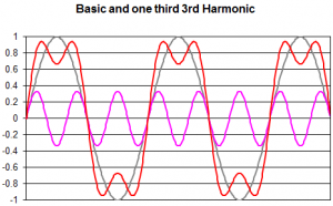
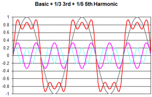
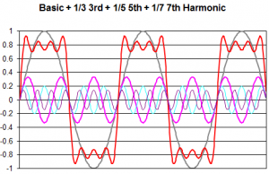
To understand this we need to ask Joseph Fourier. He was a great mathematician and proved in the 19th century that any signal curve is a function of many superimposed sinusoidal waves from different frequencies and different amplitudes. So is a square wave a superposition of the base frequency with the 3rd harmonic, the 5th harmonic, the 7th harmonic and so on. If we look closer it is the base frequency plus one third amplitude of the 3rd harmonic, one fifth amplitude of the 5th harmonic, and one seventh amplitude of the 7th harmonic – all in sync.
You may conclude the higher odd harmonics have less influence to shape the square wave, but let’s have a closer look and create an Excel sheet in 1/100 steps of a sine wave and generate graphs: